How to Optimize SiC Inverter Efficiency with Real-Time Gate-Drive
Educational | 25-08-2023 | By George Lakkas
George Lakkas - Automotive Marketing Manager for High-Power Drivers at Texas Instruments

Understanding the traction inverter basics, these devices are the main consumers of battery power in electric vehicles (EVs). Essentially, they work by converting direct current (DC) from the battery to alternating current (AC) for the electric motor, which is fundamental in how traction inverters work. This educational guide to EV traction inverters aims to shed light on their efficiency and performance. The guide to EV traction inverter efficiency reveals that the efficiency and performance of traction inverters directly impact an EV’s driving range on a single charge. As an introduction to SiC FETs in EVs, the industry has widely adopted these silicon carbide field-effect transistors due to the benefits of silicon carbide FETs in electric vehicles. Compared to traditional FETs in EVs, SiC FETs offer higher reliability, efficiency, and power density, highlighting the importance of SiC FETs in modern EV technology.
The isolated gate-driver integrated circuits (ICs) shown in Figure 1 provide low- to high-voltage (input-to-output) galvanic isolation, drive the high- and low-side power stages of each phase of a SiC-based inverter, and monitor and protect the inverter against various fault conditions. Depending on the Automotive Safety Integrity Level (ASIL) functional safety requirements, the gate-driver IC may have to be International Organization for Standardization (ISO) 26262-compliant, ensuring fault detection of ≥99% and ≥90% for single and latent faults, respectively.
In this article, I’ll delve into understanding real-time variable gate-drive strength, focusing on its benefits and its role in optimizing system parameters, a pivotal aspect of modern EV technology and a new feature that enables designers to optimize system parameters such as efficiency (which impacts EV operating range) and SiC overshoot (which impacts reliability).
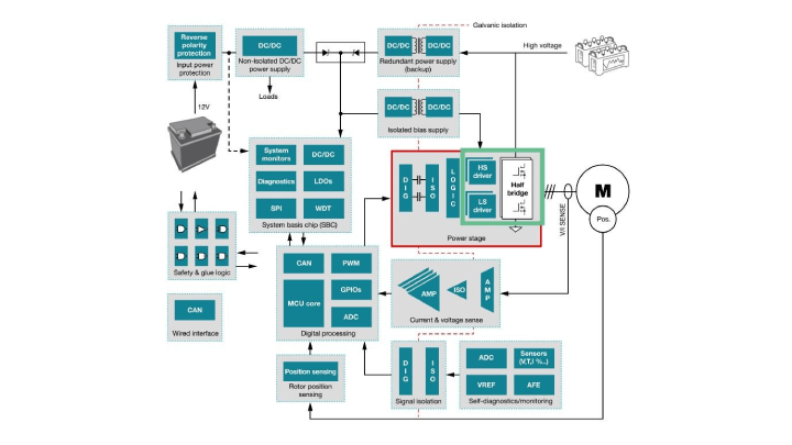
Figure 1: EV traction inverter block diagram
Higher efficiency with real-time variable gate-drive strength
The gate-driver IC has to turn on the SiC FETs as efficiently as possible while minimizing switching and conduction losses that include both turnon and turnoff energy. The ability to control and vary the gate-drive current strength reduces switching losses but at the expense of increasing transient overshoot at the switch node during switching. Varying the gate-drive current controls the slew rate of the SiC FET, as shown in Figure 2.
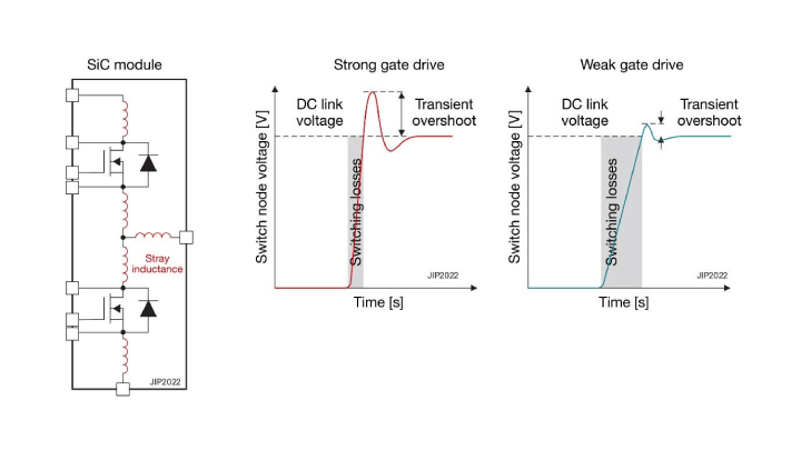
Figure 2: SiC slew-rate control by varying gate-driver IC drive strength
Real-time variability of the gate-drive current enables transient overshoot management as well as design optimization throughout the high-voltage battery energy cycle. A fully charged battery with a state of charge from 100% to 80% should use low gate-drive strength to maintain SiC voltage overshoot within the limits. As the battery charge drops from 80% to 20%, employing high gate-drive strength reduces switching losses and increases traction inverter efficiency. These scenarios are possible during 75% of the charging cycle, so the efficiency gains can be quite significant. Figure 3 illustrates a typical transient overshoot vs. battery peak voltage and state of charge.
![]()
Figure 3: Transient overshoot vs. battery peak voltage and state of charge
The UCC5880-Q1 is a 20-A SiC gate driver that has advanced protection features for traction inverters in automotive applications. Its gate-drive strength varies from 5 A to 20 A and is variable through both a 4-MHz bidirectional Serial Peripheral Interface bus or three digital input pins. Figure 4 shows the implementation through the dual split outputs that make variable gate-drive strength possible.
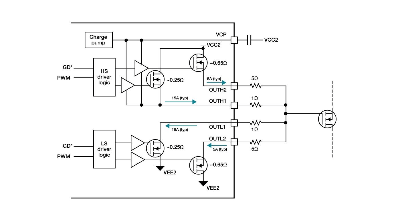
Figure 4: The UCC5880-Q1’s dual-output split gate-drive structure
Evaluating power-stage switching with DPT
A standard way to evaluate a traction inverter’s power-stage switching performance is the double pulse test (DPT), which turns the SiC power switch on and off at different currents. Varying the switching times makes it possible to control and measure the SiC turnon and turnoff waveforms over operating conditions, thus facilitating an evaluation of efficiency and SiC overshoot, which affects reliability. Figure 5 illustrates the UCC5880-Q1 variable-strength gate driver and SiC half-bridge with the low-side DPT setup.

Figure 5: Low-side DPT block diagram
The results in Table 1 show how a SiC gate driver with variable strength allows you to control overshoot while maximizing efficiency and optimizing thermal performance. EON and EOFF are the turnon and turnoff switching energy losses, respectively. VDS, MAX is the maximum voltage overshoot, and the TOFF and TON transient voltages (dv/dt) are the voltage slew rates of VDS during turnon and turnoff, respectively.
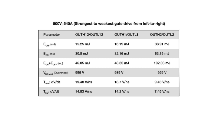
Table 1: DPT summary (800-V bus, 540-A load current, with the highest to lowest gate drive from left to right)
Mitigating overshoot
The waveforms in Figure 6 illustrate the effect of variable gate-drive strength on SiC overshoot, as the UCC5880-Q1 gate-drive resistance and drive strength are controlled in real-time. Enabling the lower gate drive (SiC turnoff) mitigates the power-stage overshoot.
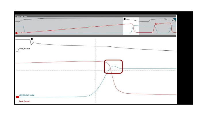
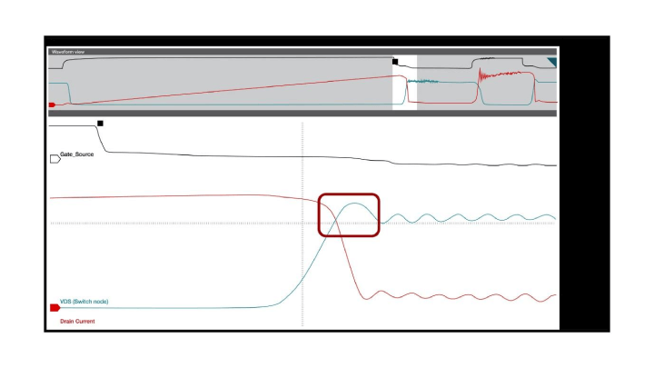
Figure 6: Real-time variable gate-drive strength effect on SiC overshoot: SiC strong drive turnoff (a); SiC weak drive turnoff (b)
Table 2 lists the actual measurements for comparison. Depending on system parasitics and goals for noise control, you can trade off between the overshoot, dv/dt and switching losses accordingly.
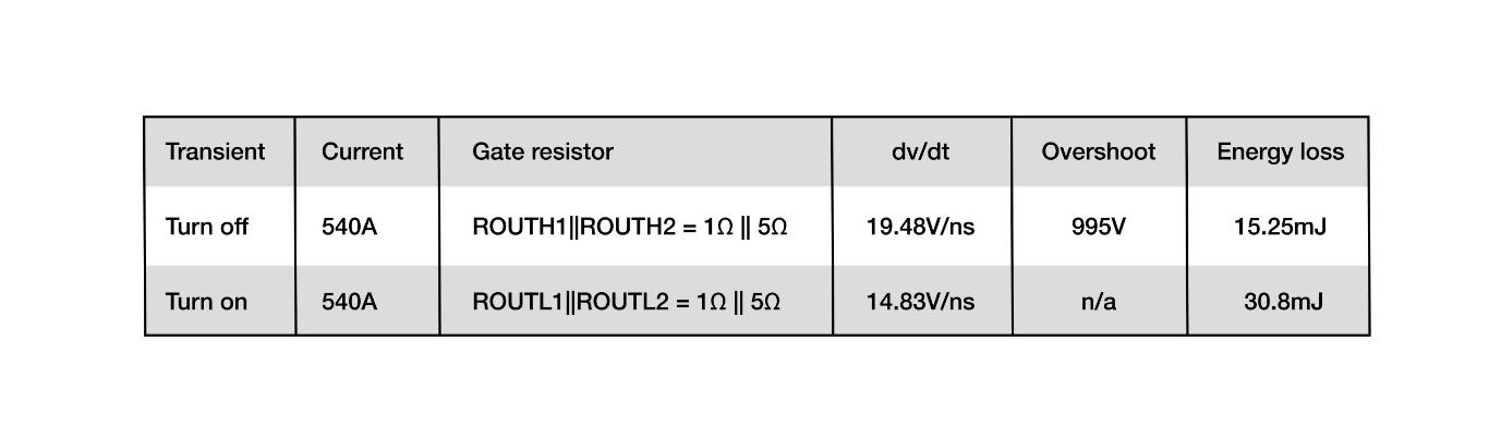
Table 2: Gate-drive strength vs. SiC FET slew rate vs. overshoot results vs. energy loss
Extending driving range
When using the UCC5880-Q1’s strong gate drive to reduce SiC switching losses, the efficiency gain can be quite significant, depending on the traction inverter’s power level. Modeling with the Worldwide Harmonized Light Vehicles Test Procedure (WLPT) and real drive log speed and acceleration settings, as shown in Figure 7, has shown SiC power-stage efficiency gains as high as 2%, corresponding to an additional 7 miles of range per battery, which can add up to over 1,000 miles per year for an EV user. Seven miles could mean the difference between a consumer reaching a charger versus getting stranded.
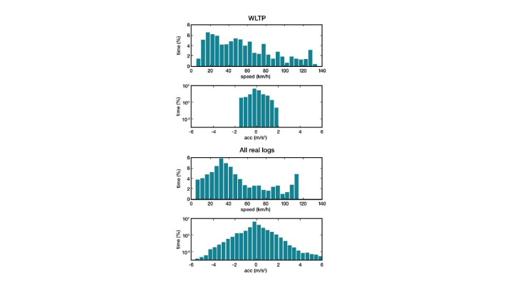
Figure 7: WLPT and real log speed and acceleration histograms
The UCC5880-Q1 also includes a SiC gate-voltage threshold monitoring feature that performs threshold voltage measurements at every EV key-on over a system’s lifetime and can provide power-switch data to the microcontroller for power-switch failure prediction.
As highlighted in the TI E2E technical article, "Improving Safety in EV Traction Inverter Systems," electric-vehicle designers can significantly enhance the safety and reliability of traction inverter systems by monitoring the gate voltage threshold. This monitoring is crucial as it serves as an early indicator of power-switch failure, ensuring the vehicle's safe operation. Furthermore, the advancements in traction inverter technology, as discussed in the white paper on "Traction Inverters – A Driving Force Behind Vehicle Electrification," have been pivotal in driving the electrification of vehicles. The integration of advanced diagnostics and protections, such as VGTH monitoring, plays a crucial role in ensuring the safety and reliability of these systems, making them more appealing to consumers and ensuring their widespread adoption.
"The inverter system’s goals and requirements ultimately determine the diagnostics and protections designed into it. Including gate voltage threshold (VGTH) monitoring into the design is an important measurement to help evaluate the state of the power module’s health throughout its lifetime."
According to the white paper on "Traction Inverters – A Driving Force Behind Vehicle Electrification," the advancements in traction inverter technology have been pivotal in driving the electrification of vehicles. The integration of advanced diagnostics and protections, such as VGTH monitoring, plays a crucial role in ensuring the safety and reliability of these systems, making them more appealing to consumers and ensuring their widespread adoption.
Conclusion
With EV traction inverters approaching 300-kW power levels, the need for higher reliability and higher efficiency is imperative. Selecting a SiC isolated gate driver with real-time variable gate-drive strength is useful in achieving these goals. The UCC5880-Q1 comes with design support tools, including evaluation boards, user’s guides and a functional safety manual to assist you with your designs.