MCB vs. eFuse: Which Works Best in DC Circuits?
Educational | 10-07-2025 | By Abdul Ücüncü
Key Takeaways:
- MCBs vs. ECBs: MCBs require peak current to trip, while ECBs respond faster and more reliably in DC circuits without needing current surges.
- Precision & Flexibility: ECBs offer adjustable tripping settings per channel and are unaffected by ambient temperature or installation spacing.
- Long-Term Efficiency: ECBs reduce downtime, simplify system expansions, and lower the total cost of ownership despite higher initial cost.
- Migration-Friendly: ECBs can directly replace MCBs with proper planning, delivering smarter protection for modern DC power systems.
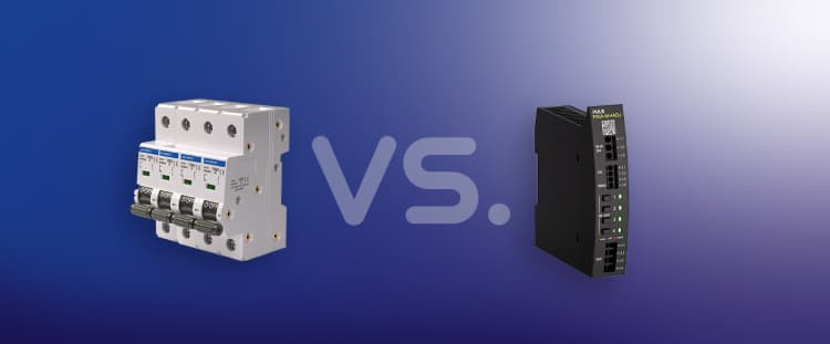
Originally published on the PULS Power Blog, this article compares a traditional miniature circuit breaker (MCB) and a modern electronic circuit breaker (ECB) with integrated eFuses. It highlights why ECBs provide faster, more reliable, and more application-appropriate protection for DC systems — without relying on peak current to trip.
In an era where unregulated transformer power supplies once dominated, traditional MCBs established themselves as the go-to protection devices. However, with the rise of switched-mode power supplies in the 1990s and the widespread adoption of DC-powered industrial systems, protection demands have shifted — and so has the technology.
This updated article explores the critical differences between MCBs and ECBs, along with practical guidance for selecting, comparing, and migrating to smarter circuit protection technologies in modern DC applications.
In times of unregulated transformer power supplies, traditional miniature circuit breakers (MCB) have established themselves as the main protection modules. However, when primarily switched-mode power supplies were introduced in the 1990s, they quickly replaced transformer power supplies in industrial applications.
The new technology enabled more efficient and compact power supplies that better met the increased demands of the industry. The era of transformers was thus over, but the MCBs remained and continued to be used in conjunction with switched-mode power supplies, even on the DC side. However, there are now much better and, above all, more reliable protection mechanisms, such as electronic circuit breakers.
MCB vs. eFuse
The biggest challenge is that miniature circuit breakers were originally designed for the AC-side of the application and require multiple times the nominal current for a few milliseconds to trip. Many switched-mode power supplies cannot provide this, as they shut down on the DC side during a high current pulse to protect themselves and the connected loads.
The alternative to the classic miniature circuit breaker (MCB) is an electronic circuit breaker (ECB) with integrated eFuses. These modules, such as our PISA models, are optimised for the distribution and protection of DC loads and do not require peak current for reliable and quick tripping. The reaction time, even with slight overload, is within 1 ms.
In this article, we explain some differences between MCBs and ECBs in detail, which can help you choose the right solution.
Real-World Use Cases for Electronic Circuit Breakers (ECBs)
While the technical differences between MCBs and ECBs are important, understanding where these devices shine in practice helps illustrate their true value. Below are three industrial use cases where ECBs offer measurable advantages over traditional MCBs.
- Automated Manufacturing Lines: In highly automated production environments, system uptime is critical. ECBs respond within milliseconds, isolating faulty channels without disrupting unaffected loads. This helps avoid full-line shutdowns due to a single tripped breaker.
- Battery Management Systems (BMS): In electric vehicles or backup power applications, DC systems demand fast, temperature-independent fault protection. ECBs are more predictable under extreme temperatures, which is vital for battery safety and longevity.
- Renewable Energy Installations: Solar inverters and wind turbine systems often use low-voltage DC circuits. ECBs can be fine-tuned to match specific load profiles, making them ideal for handling variable power conditions in these systems.
These real-world examples highlight how ECBs contribute to improved system resilience, better fault isolation, and simplified maintenance in modern industrial and energy systems.
Feature Comparison: MCB vs. ECB with Integrated eFuses
The table below summarizes the key differences between miniature circuit breakers (MCBs) and electronic circuit breakers (ECBs) to help you evaluate which protection method better suits your application.
| Feature | MCB | ECB with eFuses |
|---|---|---|
| Tripping Speed | Requires 3–10× nominal current for several ms | < 1 ms, even at slight overload |
| DC Circuit Compatibility | Requires special DC-rated models (e.g., IEC 60947-2) | Designed specifically for DC protection |
| Tripping Characteristics | Fixed (B, C, Z, etc.) | Configurable (adjustable per channel) |
| Temperature Sensitivity | Highly dependent on ambient temperature | Unaffected by ambient temperature |
| Installation Spacing | Requires derating or spacing due to heat buildup | No spacing required between modules |
| System Flexibility | Less adaptable to load changes | Highly adaptable; supports reconfiguration |
| Monitoring & Diagnostics | Not available | Often includes real-time status and trip logs |
This comparison reveals that while MCBs may be suitable for basic protection, ECBs offer greater speed, control, and intelligence — especially in dynamic DC environments where uptime and precision are critical.
Decision Guide: When to Choose an MCB or an ECB?
To help you choose the appropriate protection method for your application, use the following step-by-step guide. This decision logic is based on power supply behavior, system requirements, and fault response needs.
- 1. Is your application based on DC power?
- If yes → Go to step 2
- If no → An MCB is likely sufficient
- 2. Is fast, selective tripping essential (e.g., <1 ms)?
- If yes → Choose an ECB with eFuses
- If no → Go to step 3
- 3. Can your power supply deliver 5–10× nominal current to trip an MCB?
- If no → Choose an ECB
- If yes → Go to step 4
- 4. Is ambient temperature stable and spacing between components possible?
- If yes → An MCB may be sufficient
- If no → An ECB will offer better reliability
In summary, ECBs are the preferred solution in most modern DC applications—especially when speed, configurability, and system reliability are top priorities.
Total Cost of Ownership: Why ECBs Often Cost Less Over Time
When comparing circuit protection devices, it’s easy to focus on the unit price. However, the real cost impact lies in long-term performance, system downtime, and maintenance effort. Here's a breakdown of the cost considerations beyond the purchase price:
| Cost Factor | MCB | ECB |
|---|---|---|
| Initial Component Cost | Lower | Higher |
| Panel Space Requirements | Higher (needs spacing for cooling) | Lower (compact, no spacing needed) |
| Installation & Wiring Time | More complex (additional wiring, fuses, etc.) | Simplified with integrated protection |
| System Downtime from False Trips | High risk, especially in variable DC environments | Minimized due to precise tripping logic |
| Maintenance & Troubleshooting | Manual checks required | Status indicators and digital diagnostics available |
| Reconfiguration Flexibility | Low — fixed settings | High — adjustable per channel |
| Total Cost Over System Lifecycle | Often higher due to downtime & service | Lower — reduced failure points & higher uptime |
Although ECBs may require a higher initial investment, their benefits in uptime, serviceability, and long-term flexibility can significantly reduce total cost of ownership over the lifespan of an industrial system.
Step-by-Step Guide: Migrating from MCBs to ECBs
If you're planning to upgrade an existing installation or optimize a new design, switching from traditional MCBs to modern ECBs can increase both protection performance and system availability. Follow this simple migration workflow to ensure a smooth transition:
- Audit Your Existing Loads: Document the rated and peak current demands of each DC load and group them by criticality (essential vs. non-essential).
- Evaluate Power Supply Capabilities: Confirm the maximum output current, shutdown behavior during faults, and whether it supports fuse-breaking functionality.
- Select the Right ECB Model: Choose an ECB that offers enough channels, adjustable current limits, and tripping profiles suited to your load types. PISA-M series is a great example.
- Configure Channel Parameters: Use the ECB's interface or software (if available) to set current limits, trip delay characteristics, and reset modes for each output.
- Replace MCBs in the Panel: Remove MCBs and associated wiring/fuses, install the ECB, and connect loads to each protected channel.
- Perform Load Simulation Tests: Simulate overcurrent conditions on non-critical loads to confirm the ECB reacts as expected without disturbing other channels.
- Train Maintenance Personnel: Provide a short guide on ECB indicators, trip logs, and reset procedures to ensure fast troubleshooting during production.
Following this process helps ensure you maximize the benefits of ECBs — from improved safety and faster fault resolution to reduced system downtime and simplified expansion planning.
Common Mistakes to Avoid When Replacing MCBs with ECBs
While migrating to electronic circuit breakers (ECBs) offers many advantages, improper planning or configuration can reduce effectiveness. Here are the most common pitfalls — and how to prevent them:
- ❌ Treating ECBs like "plug-and-play" MCBs: Unlike MCBs with fixed behavior, ECBs require configuration. Failing to program current limits or delay profiles can result in improper protection.
- ❌ Overlooking power supply behavior: If the power supply cannot support the ECB’s total configured current or cannot tolerate startup inrush, tripping or system instability may occur.
- ❌ Using the wrong ECB channel allocation: Some users randomly assign loads without matching protection requirements. Assign more sensitive or critical loads to lower-current, faster-tripping channels.
- ❌ Ignoring ambient temperature limits: Even though ECBs are more tolerant than MCBs, they still have operating ranges. Placement near heat sources without airflow can still impact performance.
- ❌ Failing to train maintenance staff: ECBs often have LED status indicators or logging functions. If personnel aren't familiar with how to interpret or reset them, faults may take longer to resolve.
By avoiding these mistakes, you can unlock the full potential of ECBs and ensure your protection system delivers maximum uptime and reliability.
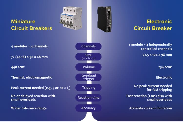
Image: 02_Comparison_MCB_PISA-M_EN.png
Approval: MCB on the DC side only with IEC 60947-2
Most circuit breakers were developed for the protection of AC circuits. The idea that the same technology can also protect DC circuits is a misconception.
The main reason is that the arc burning and arc extinguishing properties of AC and DC systems are different. An AC circuit breaker may not reliably trip in a DC circuit. Therefore, if you want to use an MCB on the DC side in industrial low-voltage systems, it must comply with the IEC 60947-2 standard. This standard applies to MCBs whose main contacts are intended for connection to circuits with rated voltages in the low-voltage range of 1,000 VAC or 1,500 VDC.
Tripping characteristic: B, C or Z?
When selecting a circuit breaker, it is important to look at the tripping characteristic. There are different tripping characteristics suitable for various industrial applications. However, to reliably protect a DC circuit, it is advisable to use an MCB with the Z tripping characteristic.
Since circuit breakers with this tripping characteristic are more expensive, MCBs with the B or C tripping characteristic are mostly used in practice. As the graph shows, circuit breakers with a Z characteristic trip at 2 to 3 times the nominal current and are significantly faster than MCBs with a B characteristic, which trip at 3 to 5 times the nominal current, or even a C characteristic, which requires 5 to 10 times the current.
With an electronic circuit breaker, the selection of the tripping characteristic is much more flexible. As part of our PISA-M series, we offer an “adjustable” version where the tripping currents and characteristics can be flexibly adjusted. Thus, the tripping speed can be chosen between a fast (max. 2 ms) and a slow (max. 10 ms) characteristic.
The current values can be individually set for each of the 4 channels, as long as the total current does not exceed 20 A. With ECBs, users can respond much more flexibly to different loads or system expansions.
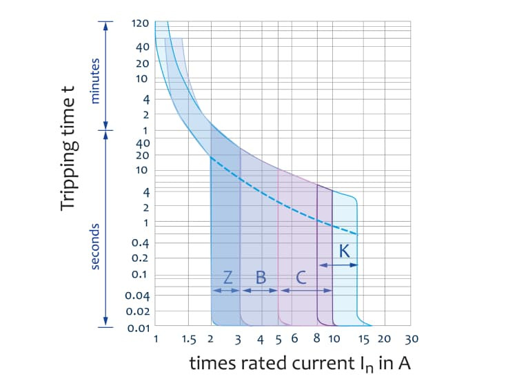
MCB: Tripping curves for B, C, Z and K characteristics
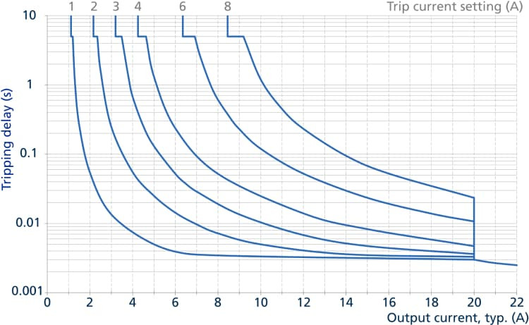
ECB: Tripping delay depending on current fast tripping characteristic.
ECB: Tripping delay depending on current slow tripping characteristic.
Tripping mechanism: Thermal, magnetic, or electrical?
A circuit breaker has two integrated types of tripping mechanisms: thermal and magnetic tripping mechanisms.
The thermal fuse is responsible for tripping the circuit breaker in case of overload. Depending on the current level, tripping can take from a few seconds to 1-2 hours. The bimetal in the circuit breaker is responsible for the thermal tripping. When the current in the circuit breaker exceeds the nominal value, the bimetal heats up and deforms, triggering the shutdown mechanism. Since the current has the same thermal effect on both DC and AC sides, the thermal tripping works the same under defined environmental conditions for both DC and AC.
The magnetic fuse is responsible for the short-circuit tripping of the circuit breaker. It is supposed to trip within a few milliseconds in a specific tripping range (each tripping characteristic has its own range). The coil in the circuit breaker is responsible for this. When a very high current flows, a strong magnetic field is formed, which trips the switch.
Since the peak value of the alternating current determines the size of the magnetic field, a correction factor for the magnetic tripping must be taken into account when using a circuit breaker in DC circuits. This correction factor is √2 or 1.41. The immediate tripping ranges for circuit breakers with different tripping characteristics are described below.
An electronic circuit breaker, on the other hand, enables simpler and more precise tripping of the channels. The ECB continuously measures the current, and the integrated eFuse reliably and quickly trips at the defined current value. This process works independently of external influences, such as ambient temperature, which is a significant advantage over MCBs. An ECB directly contributes to higher system availability.
The tripping current of MCBs is always specified as AC in the datasheet and must be multiplied by 1.41 to convert to DC values; this graphic shows the AC current and the corrected DC current.
The tripping current of MCBs is always specified as AC in the datasheet and must be multiplied by 1.41 to convert to DC values; this graphic shows the AC current and the corrected DC current.
Temperature dependence and “Rated Diversity Factor”
As explained with the thermal fuse, the bimetal responsible for tripping is temperature-dependent. This means that the higher the ambient temperature, the more the bimetal heats up and trips earlier. High ambient temperature leads to the maximum nominal current flowing through the circuit breaker, which needs to be reduced to prevent unwanted tripping. Conversely, at low temperatures, a higher current must flow to sufficiently heat the bimetal to trip the circuit breaker.
The installation situation in the control cabinet can also affect the thermal fuse. When multiple circuit breakers are operated side by side without spacing, thermal interaction occurs between them. The circuit breakers heat each other, which means the maximum nominal current of the circuit breakers must be reduced again. How much the current needs to be reduced due to increased temperature of the MCB in such cases is specified by the manufacturer and referred to as the Rated Diversity Factor (RDF).
Electronic circuit breakers, on the other hand, are temperature-independent. The operating temperature of the PISA-M is between -25 °C and +70 °C at full output power, i.e., without derating. An A-rated Diversity Factor is not necessary.
The modules can also be installed in the control cabinet without a minimum spacing to other PISA-M units. Only a minimum distance of 15 mm to heat sources, such as the power supply, must be maintained.
Choosing the right power supply unit
Just as important as selecting the right circuit breaker is the decision for the appropriate power supply unit. This aspect is often overlooked.
Practice shows that the short-circuit current of a 10 A power supply for a total load of 7 A may not be sufficient to trip the MCB and isolate the faulty load. Because with a load of 7 A, a 10 A MCB is usually used. This means that if an MCB with the B characteristic is used, the 10 A power supply would need to provide between 30 A and 50 A as short-circuit current to trip the MCB. Most 10 A power supplies cannot provide this much current, as they shut down for self-protection beforehand. As a result, all loads connected to the power supply are no longer supplied, even if they do not have a fault.
To avoid this problem, a power supply with a fuse-breaking feature can be used, which provides 5-6 times the nominal current for a few milliseconds. Alternatively, the power supply must be oversized. This means using a higher power class. Both solutions have their disadvantages: users may pay for functions they do not need, and a larger power supply requires more space in the system. Even with a perfectly matched power supply to the MCBs, it may happen that the short-circuit current is not sufficient to trip the circuit breaker, for example, if the total resistance of the short-circuit path is too high.
If you want to combine a power supply with an electronic circuit breaker, only the available maximum output current of the power supply is relevant for the decision. For an ECB of the PISA-M type, we recommend a power supply with at least 90 W output power. The selection is thus much more flexible.
The 480 W DIN rail power supply CP20.248 features easy fuse breaking with 3 times the nominal current for 12 ms.
Summary:
Choosing the right circuit breaker requires a precise understanding of the application and careful system planning. All this takes time, engineering resources, and ultimately money.
With every small change in the application, it must be determined again whether the circuit breakers still provide sufficient protection for the existing loads. With an electronic circuit breaker, this effort can be significantly reduced. In addition to wiring, only the configuration of the output currents needs to be done.
Our PISA modules with integrated eFuses protect loads by reliably tripping affected channels, regardless of the load, temperature, power supply, or total resistance of the short-circuit path.