Generating Sub-1V Power
| 11-11-2020 | By Mark Patrick
Digital electronics have come a long way in performance and power supply requirements. The original 8086 processor, with its 10MHz maximum clock speed and 3µm process, used 5V for the core and I/O functions and dissipated just 1.8 watts. This ‘single plane’ power supply design gradually reduced to 3.3V over its lifetime. With the pressure to minimise power consumption in laptops and mobile devices, dual-plane arrangements were adopted, enabling the core to run at a lower voltage, while the I/O remained at 3.3V. For today’s processors, with a 4GHz clock and a 7nm process, the core supply is now less than 1V and peak power around 140 watts.
While the push to lower voltage minimises power consumption, it also reduces speed capability. Higher voltages stress metal oxide insulators in the CPU transistors and increase leakage and power loss due to ‘tunnelling’ effects; insulation layer thickness is typically only 0.5nm or around the dimension of two atoms. To provide the ever-increasing performance demanded, but at low supply voltages, parallel processing in multi-core CPUs running multiple threads of code is the norm, multiplying overall power and current consumption.
A centralised power supply was appropriate for single plane arrangements, and accuracy was maintained at the ICs with the low voltage drops of connections at low current. As voltages fell, current increased and accuracy specifications became tighter. 'Intermediate bus' arrangements became necessary to route voltage around a system at a higher level, typically 12V and at lower current, then a DC-DC converter dropped the voltage to the operating level close to the load.
In telecommunications environments, supplies have to be reliable and minimise monetary and environmental cost, forcing a significant change of power architectures as computing technology has evolved. Before the early 1990s, centralised power supplies were standard, with an AC-DC rectifier generating a -48V bus which had battery back-up (Figure 1a). A DC-DC converter then provided lower voltages, typically 5V and +/-12V, to shelves in cabinets. Static and dynamic regulation was poor, and single component failures could take the whole system offline. Consequently, a Distributed Power Architecture (DPA) was devised, routing battery-backed -48V to each shelf with isolated DC-DC converters on cards providing end-voltages (Figure 1b). Redundant cards could now be hot-swapped leaving the system in operation with tight voltage regulation at the loads. Many isolated DC-DC converters resulted in a higher cost, so hybrid arrangements of centralised and DPA were sometimes used.
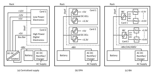
Figure 1: Evolution of power architectures.
The next enhancement was an intermediate bus architecture (IBA) (Figure 1c), where isolation and down-conversion to an intermediate voltage of typically 5V or 12V are provided by a single 'bus' (IBC) converter on each card. Low-cost, non-isolated DC-DCs or Point of Load (PoL) converters then provide the end-voltage. The bus converter was supplied by -48V, 24V or even 400V to keep primary current and conduction losses low. The converter could be fully-, semi-, or un-regulated, depending on the application, as the PoL converters are typically wide-input and do not need a tightly regulated supply.
Modern Power Architectures
IBA is common today with variants of bus converters designed to provide the best overall efficiency in the application. As loads inevitably increase, 12V intermediate bus voltages have become problematic with the high currents involved, so more recent designs tend to increase the bus to 48V and specify PoL converters that drop this voltage, in the extreme, directly to sub-1V levels. The high conversion ratio produces short pulses and high peak currents in the converter and would have been impractical just a few years ago due to efficiency considerations. However, as semiconductors and power conversion topologies have advanced, the approach is now seen as viable, especially when the reduced bus ohmic losses, size and cost are factored in. Where justified on efficiency grounds, cascaded stages of PoL can be used. For example, 48V to 3.3V required for I/O, feeding another PoL 3.3V to 1.8V. System designers will generate a ‘power tree’ to represent their proposed architecture - an example is in Figure 2 for a Xilinx SoC (System on Chip).
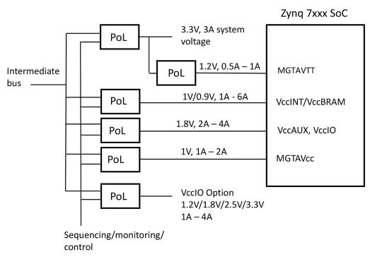
Figure 2: A typical ‘power tree’ for a Xilinx SoC device.
PoL Specifications
The PoL used for IBA must meet tight specifications for output noise, voltage tolerance, and static and dynamic regulation. Typical requirements are to maintain the output within +/-3% under all conditions for the most sensitive loads, such as DSPs running with a 1V core supply with load steps of 5A or more. The converter control loop must be fast, implying high switching frequency which in turn mandates use of high-performance semiconductors, perhaps using the latest wide-bandgap types for best efficiency. The PoL should have the ability to be 'sequenced' with other PoLs so that power rails rise and fall in the correct order. Increasingly, a CPU needs to communicate with the PoL for dynamic adjustment of the output voltage and to monitor performance such as output current, temperature and fault flags, typically using PMBusTM commands over an I2C interface. Latest PoL designs will also feature digital loop control for the optimum performance with changing loads and varying output capacitance for different applications or as conditions change over time. The control and monitoring in a PoL are therefore complicated. Even the basic topology of a classic ‘buck’ converter will be enhanced by synchronous rectification and multiphase operation for acceptable efficiency at high load currents while keeping light load losses low.
PoL converter specifications vary somewhat with the load; CPUs, FPGAs, ASICS, SoC and ACAP devices all have their particular demands. In every case, the converter must be fitted as close as possible to the load for best performance, presenting a problem in board layout with the array of address and I/O lines that need accommodating. PoLs, therefore, must be very compact. For this reason, discrete component versions of PoLs are rarely viable, with modules being a natural choice. This approach also has the benefits of enabling the use of more vertical space with parts that are pre-tested and certified and with industry-standard footprints. The technology necessary in PoLs also requires meticulous board arrangements for power planes, screen layers and tight current loops in the power stage for EMI mitigation. These features are easier to implement in the substrate of a module dedicated to the task than in the motherboard. With a typical PoL comprising 100+ components, stockholding and procurement of a module are also significantly more straightforward than with a discrete solution.
Hybrid solutions are available where the power stage can be bought as a module, compatible with third-party power management and control IC. Here, the IC is placed on the motherboard and the module is placed over it or sometimes on the opposite of the motherboard.
PoL Formats – The Alternatives
PoL converters are available in through-hole or pluggable SIP formats, occupying a minimum of board space, such as the ranges from Texas Instruments, RECOM, CUI, TRACO, Murata, ABB, XP Power, Advanced Energy and many others. Surface mount modules are preferred for the economy of manufacturing, and there are various options including gull-wing, block feet, LGA and iLGA (Inspectable Land Grid Array). Outputs are available down to fractions of a volt and currents to over 40A.
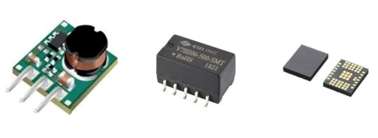
Figure 3: Different example PoL formats: left, TI TPSM series, middle, CUI V78E series, right, Murata MYMG series.
As an example, the Murata MYMGA ‘monoblock’ series delivers 12A from an LGA package just 10.5 x 9.0 x 5.6mm. The parts feature input ranges of 4.5 to 8V or 8 to 15V, and the output can be trimmed from 0.7 to 1.8V with efficiency peaking at 93.5%. Matching in with the FPGA/CPU requirements for accurate voltage rails, the series offers maximum load regulation of +/-1% (Figure 4).
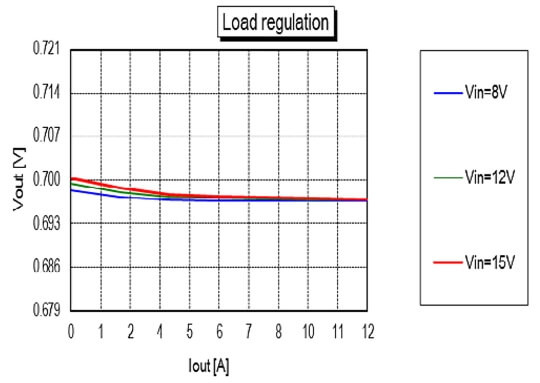
Figure 4: Murata MYMGA variants offer +/-1% load regulation. (Source: Murata)
A PoL converter from Texas Instruments in a through-hole format, the PTH08T250W, also features tight load regulation of +/-1.5% but over the output load range of 0 to 50A with the option to parallel modules for even higher currents. The part has an input range of 4.5 to 14V and an adjustable output between 0.7V and 3.6V with an efficiency of up to 96%. Both the Murata and Texas Instruments parts suit IBA arrangements where the bus voltage is loosely regulated, leading to enhanced overall efficiency.
All converters have comprehensive protection features, and some comply with common performance and pin-out standards defined by DOSA (Distributed power Open Standards Alliance). A feature to look out for is the ability to start up into pre-biased loads, which can occur in systems with multiple voltage rails. The more complex PoL converters include more monitoring and control such as the ‘Tunable LoopTM’ feature in the ABB ‘Lynx’ series, allowing user-adjustment of the voltage control loop to maximise dynamic performance while minimising output capacitance for any particular load.
Modular PoL suppliers will typically make demonstration boards available with GUI interfaces for the set-up of loop response and control and monitoring parameters.
Summary
Modern processors and programmable ICs have dramatic performance and are now ubiquitous everywhere from infotainment to telecommunications and industry. Providing power has challenged DC-DC converter designers with ever-lower voltages and higher currents. The problem is addressed explicitly by modular PoL converters that match-in with bus architectures to give clean, high-performance voltage rails with high conversion efficiency. All this while providing an economical solution compared with discrete components. Built-in intelligence adds further value by adapting PoL performance to load requirements and adding control commands and status signalling.